Flash Management
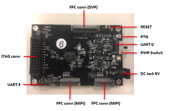
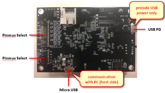
1. Board Overview
2. Hardware Setting
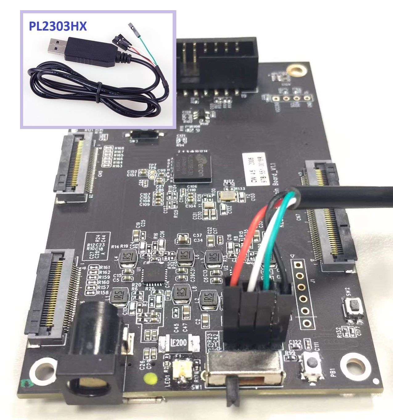
2.1. Connecting UART0 (Program Flash via UART0 Interface)
- UART0: Command Port
- The UART Tx/Rx definition may be different from various vendors. If your USB-UART cable doesn't work, please swap Tx/Rx pin, re-plug and try again.
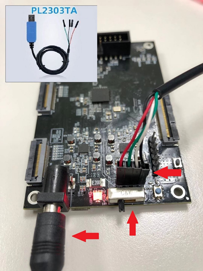
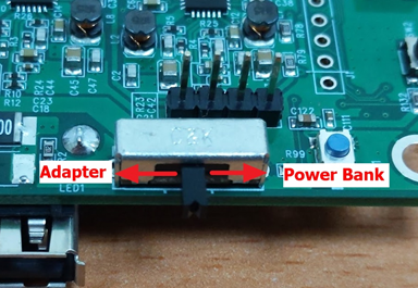
2.2. Connecting 5V power and trun on power switch
Power from Adapter or from Power Bank (USB PD)
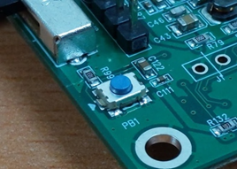
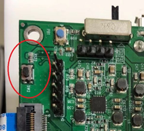
2.3. Wake up chip from RTC power domain by pressing PTN button
Please do it every time after plugging in the power
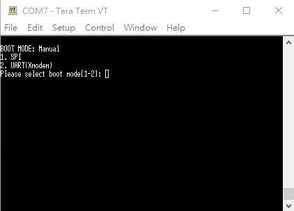
2.4. Set bootstrap settings to manual boot mode (Program Flash via UART0 Interface)
- Must set bootstrap settings to manual boot mode
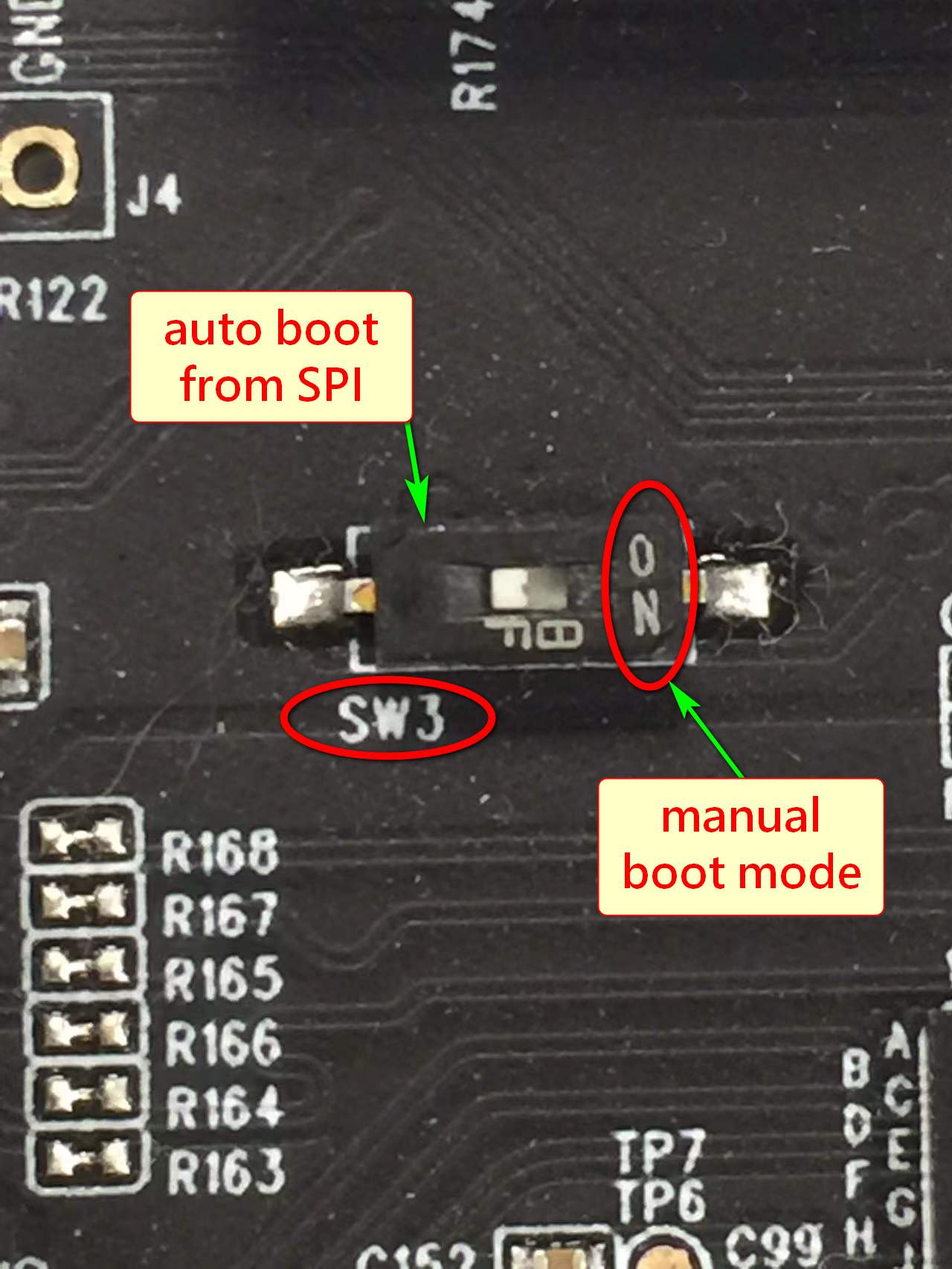
- Reset pin or power must be controllable to enter manual boot mode.
3. Program Flash via UART0 Interface
3.1. Flash programmer necessaries
- Open command terminal for flash programmer execution
Tool path:
kl520_sdk\utils\flash_programmer\flash_programmer.py - Install Necessary python modules:
kl520_sdk\utils\requirements.txt - Limitations: Only the listed argument combinations below are allowed.
3.2. Edit python verification setting
-
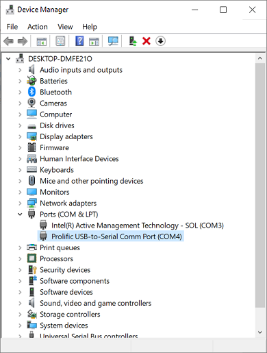
Check UART port number from device manager
-
Edit setup.py, search “COM_ID” and modify the ID to match your UART port number
EX: COM_ID = 4 # COM4
3.3 Firmware Binary Generation (FW + MODELS)
Generate flash final bin file from other seperate bin files. The script combines .bin files in "flash_bin" in predefined order. Morever, the addressing is in 4KB alignment
Command
$ python3 bin_gen.py

    options argument:

    -h, --help      Show this help message and exit
    -p, --CPU_ONLY  SPL/SCPU/NCPU only
Output
flash_image.bin
Note The following bin files are must
flash_bin/
├── boot_spl.bin        // bool spl bin file
├── fw_ncpu.bin         // SCPU FW bin file (generated by Keil)
├── fw_scpu.bin         // NCPU FW bin file (generated by Keil)
├── models_520.nef      // model information(copied from [host_lib]/input_models/KL520/[app]/)
3.4 Firmware Binary Generation for KDP2 (FW + MODELS)
Generate flash final bin file from other seperate bin files. The script combines .bin files in "flash_bin" in predefined order. Morever, the addressing is in 4KB alignment
Command
$ python3 kdp2_bin_gen.py

    options argument:

    -h, --help      Show this help message and exit
    -p, --CPU_ONLY  SPL/SCPU/NCPU only
Output
kdp2_flash_image.bin
Note The following bin files are must
flash_bin/
├── boot_spl.bin                        // bool spl bin file
├── kdp2_fw_loader.bin                  // LOADER bin file (generated by Keil or copied from plus/res/firmware/KL520)
├── kdp2_fw_ncpu.bin                    // SCPU FW bin file (generated by Keil)
├── kdp2_fw_scpu.bin                    // NCPU FW bin file (generated by Keil)
├── kdp2_prog_fw_loader_flash-boot.bin  // switch to flash boot bin file (copied from kl520_sdk/utils/JLink_programmer/kdp2)
├── models_520.nef                      // model information (copied from plus/res/models/KL520)
3.5 Flash Chip Programming (FW + DATA)
$ python flash_programmer.py -a flash_image.binPlease press RESET BTN while you are seeing “Please press reset button!!”
Afterwards, just wait until all progresses are finished (erase, program, verify)
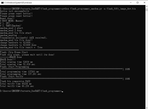
Note
flash_programmer.py -ameans to do flash chip erase + programming + verification
3.6 Flash Verification (optional)
$ python flash_programmer.py -v flash_image.bin3.7 Flash Erase (optional)
$ python flash_programmer.py -e3.8 Flash Partial Programming (optional)
$ python flash_programmer.py -i 0x00002000 -p fw_scpu.bin

# "**-i**" means the flash index/address to program
# "**-p**" means the FW binary to program
4. Program Flash via JTAG/SWD Interface
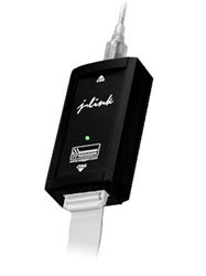
4.1. Jlink programmer necessaries
Connect JTAG/SWD.
4.2. Edit flash_prog.jlink device setting
-
Check your flash manufacturer: Winbond or Mxic or GigaDevice
-
Select a specific device based on flash manufacturer
EX:
device KL520-WB  //Winbond
device KL520-MX  //Mxic
device KL520-GD  //GigaDevice
Copy the bin file to kl520_sdk\utils\JLink_programmer\bin folder
EX: flash_image.bin, boot_spl.bin, fw_scpu.bin, fw_ncpu.bin, etc.
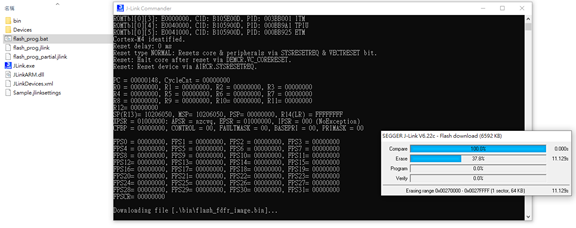
4.3. Double click "flash_prog.bat"
Afterwards, just wait until all progresses are finished (chip erase, program, verify)
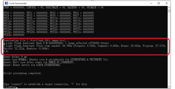
4.4. Check programming result
Please ensure all the results are "O.K.", and enter "qc" to quit and close J-Link commander
4.5. Edit flash_prog_partial.jlink device setting(optional)
To program specific bin file to specific flash address
-
Copy the bin file to
kl520_sdk\utils\JLink_programmer\bin\ -
Select a specific device+’-P’ based on flash manufacturer
EX:
device KL520-WB-P    //Winbond
device KL520-MX-P    //Mxic
device KL520-GD-P //GigaDevice- Edit loadbin command: Load *.bin file into target memory
Syntax:
loadbin <filename>, <addr>
loadbin .\bin\boot_spl.bin,0x00000000
loadbin .\bin\fw_scpu.bin,0x00002000
loadbin .\bin\fw_ncpu.bin,0x00018000-
Double click “flash_prog_partial.bat” and wait until all progresses are finished
-
Check programming result
Please ensure the results is “O.K.”, and enter “qc” to quit and close J-Link commander
5. Program Flash via JTAG/SWD Interface for KDP2
5.1. Jlink programmer necessaries
Connect JTAG/SWD.
5.2. Copy the bin file
Copy all bin files to kl520_sdk\utils\JLink_programmer\bin\ folder
- kdp2_flash_image.bin
- kdp2_fw_loader.bin
- kdp2_fw_ncpu.bin
- kdp2_fw_scpu.bin
Note: Please refer 3.4 Firmware Binary Generation for KDP2 (FW + MODELS)) to generate kdp2_flash_image.bin.
5.3. Program Flash Using United Bin File
-
Check your flash manufacturer: Winbond or Mxic or GigaDevice
-
Goto folder
kl520_sdk\utils\JLink_programmer\ -
Select a specific device based on flash manufacturer to kdp2\kdp2_flash_prog.jlink
EX:
device KL520-WB  //Winbond
device KL520-MX  //Mxic
device KL520-GD //GigaDevice-
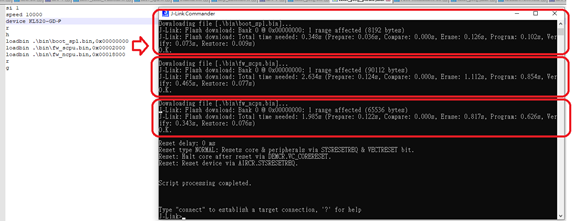
Execute kdp2_flash_prog.bat and wait until all progresses are finished (chip erase, program, verify)
-
Check programming result to ensure all the results are "O.K.", and enter "qc" to quit and close J-Link commander
5.4. Program Flash Using Partial Bin Files to Usb Boot
-
Check your flash manufacturer: Winbond or Mxic or GigaDevice
-
Goto folder
kl520_sdk\utils\JLink_programmer\ -
Edit kdp2\kdp2_prog_fw_loader_usb-boot.jlink
-
Select a specific device+’-P’ based on flash manufacturer to
EX:
device KL520-WB-P    //Winbond
device KL520-MX-P    //Mxic
device KL520-GD-P //GigaDevice- Edit loadbin command: Load *.bin file into target memory
Syntax:
loadbin <filename>, <addr>
loadbin ..\bin_gen\flash_bin\boot_spl.bin,0x00000000
loadbin .\bin\kdp2_fw_loader.bin,0x00002000
loadbin .\kdp2\kdp2_prog_fw_loader_usb-boot.bin,0x00029000
loadbin .\bin\kdp2_fw_loader.bin,0x00041000-
Execute kdp2_prog_fw_loader_usb-boot.bat and wait until all progresses are finished (chip erase, program, verify)
-
Check programming result to ensure all the results are "O.K.", and enter "qc" to quit and close J-Link commander
5.5. Program Flash Using Partial Bin Files to Flash Boot
-
Check your flash manufacturer: Winbond or Mxic or GigaDevice
-
Goto folder
kl520_sdk\utils\JLink_programmer\ -
Edit kdp2\kdp2_prog_fw_loader_flash-boot.jlink
-
Select a specific device+’-P’ based on flash manufacturer to
EX:
device KL520-WB-P    //Winbond
device KL520-MX-P    //Mxic
device KL520-GD-P //GigaDevice- Edit loadbin command: Load *.bin file into target memory
Syntax:
loadbin <filename>, <addr>
loadbin ..\bin_gen\flash_bin\boot_spl.bin,0x00000000
loadbin .\bin\kdp2_fw_loader.bin,0x00002000
loadbin .\kdp2\kdp2_prog_fw_loader_flash-boot.bin,0x00029000
loadbin .\bin\kdp2_fw_scpu.bin,0x00030000
loadbin .\bin\kdp2_fw_loader.bin,0x00041000
loadbin .\bin\kdp2_fw_ncpu.bin,0x00068000-
Execute kdp2_prog_fw_loader_flash-boot.bat and wait until all progresses are finished (chip erase, program, verify)
-
Check programming result to ensure all the results are "O.K.", and enter "qc" to quit and close J-Link commander