Getting Started
1. Environment Setup
There are several ways to get the Kneron host example:
-
Get the example folder for Linux environment
Prerequisite: Cmake, OpenCV
Download the code here: [kl520_sdk_v1.3.zip] -
Get the VM for the windows and Mac
Prerequisite: VMware Workstation
Download the VM total five files :Part1 Part2 Part3 Part4 Part5Map USB port and share drive into VM: Link
2. File Structure
In the Kneron folder, you will see the following file folders:
Kneron-|
       |->app_binaries-|        (KL520 app binaries for example)
                       |-> tiny_yolo_v3
                       |-> ota/ready_to_load
                       |-> ...
       |-> common               (common shared file between host and KL520)
       |-> dll                  (dll files for Windows MSYS2)
       |-> docs                 (images in README)
       |-> example              (host program for different C++ examples)
       |-> pkgs                 (Python whl files for different platforms)
       |-> python               (host program for different Python examples)
       |-> src                  (source files for host lib, which communicate with KL520)
       |-> test_images          (test image binary)
       |-> CMakeList.txt        (top level cmake list)
       |-> README_CPP.md        (simple instruction to build for C++ examples)
       |-> README_Python.md     (simple instruction for Python examples)
3. Compile and Build
This project use cmake to build the code. There is top level CMakelist.txt, and src folder and example folder have their own CMake List. Src folder cmake list is for building the host lib to communicate with KL520. Users usually do not need to modify files under this folder unless they would like to modify the communication protocol. For the example folder, users can modify the cmake list to add more test or their application.
Use Cmake to build:
mkdir build
cd build
cmake ../ # or 'cmake -DBUILD_OPENCV_EX=on ..' to build with opencv applicaiton
make -j
And then you will see the bin directory, and all the example executables are under here.
4. Run the Default Application Tiny Yolo v3
Tiny Yolo v3 is an object detection algorithm, and it can classify 80 different classes. Kneron device come with build-in binaries that can run 608x608 RGB565 image in Tiny Yolo v3 object detection.
Here is the class list: Link
4.1 C++ Example
Let’s take a look at the C++ example program, isi_async_parallel_yolo.cpp. In this test, we send two different images image_608_1.bin and image_608_2.bin (two RGB565 bianries) into KL520, and get the detection results back.
#define TEST_ISI_DIR        "../../test_images/odty/"
#define ISI_IMAGE_FILE      (TEST_ISI_DIR "image_608_1.bin")
#define ISI_IMAGE_FILE_T    (TEST_ISI_DIR "image_608_2.bin")
#define IMG_SOURCE_W        608
#define IMG_SOURCE_H        608
#define ISI_IMG_SIZE        (IMG_SOURCE_W * IMG_SOURCE_H * 2)
#define ISI_APP_ID          APP_TINY_YOLO3
// isi initial result memory size in bytes
#define ISI_RESULT_SIZE     2048
After we setup the images and image buffer size, the program uses kdp_start_isi_mode to notify the communication and inference setup.
uint16_t width  = IMG_SOURCE_W;
uint16_t height = IMG_SOURCE_H;
// image format flags
// IMAGE_FORMAT_SUB128: subtract 128 for R/G/B value in Kneron device
// NPU_FORMAT_RGB565: image input is RGB565
// IMAGE_FORMAT_PARALLEL_PROC: pipeline between ncpu and npu
uint32_t format = IMAGE_FORMAT_SUB128 | NPU_FORMAT_RGB565 | IMAGE_FORMAT_PARALLEL_PROC;

// Flash the firmware code with companion mode for tiny_yolo_v3 !!!
printf("starting ISI mode ...\n");
// call kdp_start_isi_mode to start isi mode
int ret = kdp_start_isi_mode(
    dev_idx, ISI_APP_ID, ISI_RESULT_SIZE, width, height, format, &error_code, &image_buf_size);
if (ret != 0) {
    printf("could not set to ISI mode: %d ..\n", ret);
    return -1;
}

if (image_buf_size < 3) {
    printf("ISI mode window %d too small...\n", image_buf_size);
    return -1;
}

printf("ISI mode succeeded (window = %d)...\n", image_buf_size);
usleep(SLEEP_TIME);
Setup image buffer to load the image binaries.
int n_len = read_file_to_buf(img_buf1, ISI_IMAGE_FILE, ISI_IMG_SIZE);
if (n_len <= 0) {
    printf("reading image file 1 failed:%d...\n", n_len);
    return -1;
}

n_len = read_file_to_buf(img_buf2, ISI_IMAGE_FILE_T, ISI_IMG_SIZE);
if (n_len <= 0) {
    printf("reading image file 2 failed:%d...\n", n_len);
    return -1;
}
Since the KL520 application design use image buffer to pipeline the image transfer and npu processing, we can fill up the image buffer first. Therefore, we can use kdp_isi_inference to send images to KL520, without getting the result back yet.
printf("starting ISI inference ...\n");
uint32_t img_id_tx = 1234;
uint32_t img_id_rx = img_id_tx;
uint32_t img_left = 12;
uint32_t result_size = 0;
uint32_t buf_len = ISI_IMG_SIZE;
char inf_res[ISI_RESULT_SIZE];

// start time for the first frame
double start_time = what_time_is_it_now();

// Send 2 images first
// do inference for each input
ret = do_inference(dev_idx, img_buf1, buf_len, img_id_tx, &error_code, &img_left);
if (ret)
    return ret;
img_id_tx++;
// do inference for each input
ret = do_inference(dev_idx, img_buf2, buf_len, img_id_tx, &error_code, &img_left);
if (ret)
    return ret;
img_id_tx++;

// Send the rest and get result in loop, with 2 images alternatively
uint32_t loop = 0;
if (test_loop > 3)
    loop = test_loop - 2;

while (loop) {
    // do inference for each input
    ret = do_inference(dev_idx, img_buf1, buf_len, img_id_tx, &error_code, &img_left);
    if (ret)
        return ret;
    img_id_tx++;
Then the program must wait and get back the result then send the next image. It uses kdp_isi_retrieve_res to get the result, then check the result if it matches the expected results. After that, it uses kdp_isi_inference to send another images to KL520 to process. The loop is set to 1000 to estimate the average FPS of 1000 images.
    ret = do_get_result(dev_idx, img_id_rx, &error_code, &result_size, inf_res);
    if (ret)
        return ret;
    img_id_rx++;

    loop--;
    // Odd loop case
    if (loop == 0)
        break;
    // do inference for each input
    ret = do_inference(dev_idx, img_buf2, buf_len, img_id_tx, &error_code, &img_left);
    if (ret)
        return ret;
    img_id_tx++;

    // retrieve the detection results for each input
    ret = do_get_result(dev_idx, img_id_rx, &error_code, &result_size, inf_res);
    if (ret)
        return ret;
    img_id_rx++;

    loop--;
}
Lastly, the program needs to retrieve all the remaining image results, using kdp_isi_retrieve_res.
// Get last 2 results
// retrieve the detection results for each input
ret = do_get_result(dev_idx, img_id_rx, &error_code, &result_size, inf_res);
if (ret)
return ret;
img_id_rx++;
// retrieve the detection results for each input
ret = do_get_result(dev_idx, img_id_rx, &error_code, &result_size, inf_res);
if (ret)
return ret;
img_id_rx++;
// calculate the FPS based on the time for 1000 frames
if (1) {
double end_time = what_time_is_it_now();
double elapsed_time, avg_elapsed_time, avg_fps;
elapsed_time = (end_time - start_time) * 1000;
avg_elapsed_time = elapsed_time / test_loop;
avg_fps = 1000.0f / avg_elapsed_time;
printf("\n=> Avg %.2f FPS (%.2f ms = %.2f/%d)\n\n",
avg_fps, avg_elapsed_time, elapsed_time, test_loop);
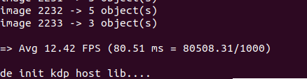
}Run the executable binaries, and we can see initialization messages, and the buffer depth is 3. Image index is keep increasing and the expected 5 and 3 objects are toggling because we ping pong transfer two images, so the results are ping pong as 5 objects and 3 objects as well
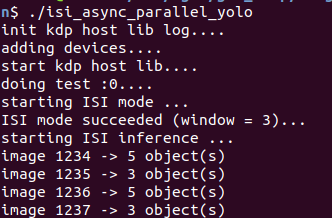
Lastly, we can see the average FPS for running 1000 images is 12.4, each image take average 81ms to finish.
4.2. Python Example
Let’s take a look at the Python example program, cam_isi_async_parallel_yolo.py. In this test, we send frames (RGB565) of camera into KL520, and get the detection results back.
Setup video capture device for the image width and height
"""User test cam yolo."""
image_source_h = 480
image_source_w = 640
app_id = constants.APP_TINY_YOLO3
image_size = image_source_w * image_source_h * 2
frames = []

# Setup video capture device.
capture = kdp_wrapper.setup_capture(0, image_source_w, image_source_h)
if capture is None:
    return -1
After we setup the video capture device, the program uses start_isi_parallel to notify the communication and inference setup.
# Start ISI mode.
if kdp_wrapper.start_isi_parallel(dev_idx, app_id, image_source_w, image_source_h):
    return -1
Since the KL520 application design use image buffer to pipeline the image transfer and npu processing, we can fill up the image buffer first. Therefore, we can use fill_buffer to send frames to KL520, without getting the result back yet.
start_time = time.time()
# Fill up the image buffers.
ret, img_id_tx, img_left, buffer_depth = kdp_wrapper.fill_buffer(
    dev_idx, capture, image_size, frames)
if ret:
    return -1
Then the program must wait and get back the result then send the next image. It uses pipeline_inference to get the result and to send another images to KL520 to process. The loop is set to 1000 to estimate the average FPS of 1000 images.
# Send the rest and get result in loop, with 2 images alternatively
print("Companion image buffer depth = ", buffer_depth)
kdp_wrapper.pipeline_inference(
dev_idx, app_id, test_loop - buffer_depth, image_size,
capture, img_id_tx, img_left, buffer_depth, frames, handle_result)
end_time = time.time()
diff = end_time - start_time
estimate_runtime = float(diff/test_loop)
fps = float(1/estimate_runtime)
print("Parallel inference average estimate runtime is ", estimate_runtime)
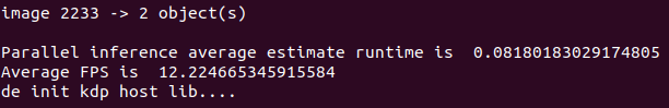
print("Average FPS is ", fps)Run the Python example, and we can see initialization messages, and the buffer depth is 3. Image index keeps increasing and the number of detected objects are outputted
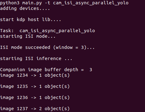
Lastly, we can see the average FPS for running 1000 images is 12.2, each image take average 82ms to finish.
5. Run OTA to Swap Another Pre-build Application Binary Mask Face Detection
Besides Tiny Yolo v3, Kneron also provides many other applications:
- Age_gender: detect faces and return age and gender estimation of the target face
- Objection_detection: Kneron 8 class detections
- Pedestrian_detection: Kneron pedestrian detection
- Ssd_fd: Mask face detection, detect face with mask and without mask

In order to swap the KL520 application, Kneron provides update application feature to update the firmware via USB. Here is an introduction how to do it.
First, user can copy the target application into app_binaries/ota/ready_to_load. Here we will load the mask fd application into KL520. As you can see, there are 3 files, fw_ncpu.bin fw_scpu.bin, and model_ota.bin. Fw_ncpu.bin and Fw_scpu.bin are program binaries that run in the two cpu in KL520. And model_ota.bin is the binary for deep learning models.

Then we can go to build/bin, and run ./update_app. This will load all 3 binaries into KL520, and program them into the flash so that even without power, the KL520 can still maintain the applications. Since the model are relatively large and flash programming is slow, users need to wait for couple mins to update the application. It takes about 3 minutes here.
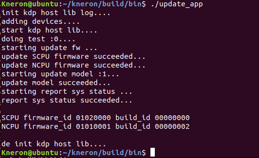
As you can see the log, the SCPU and NCPU firmware are updated successfully, and model update successfully. Last, it will print out the SCPU firmware id and NCPU firmware id to ensure it is updated with the correct version of code. After KL520 is updated with the mask face detection, we can start to run this corresponding example. We are going to try the interactive with camera example, therefore, we will make sure we build the apps require opencv. Make sure to do “cmake -DBUILD_OPENCV_EX=on ..” and “make -j” again to make the cam application.

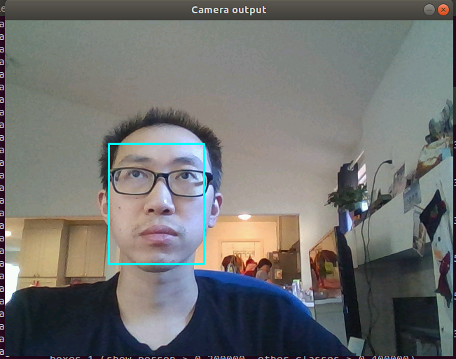
A Camera output window will pop out and use light blue box to get the human face.
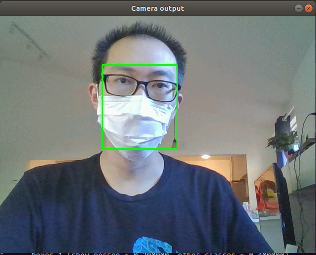
And when you put on the mask, there will be a green bounding box around the human face. After 1000 inference, the program will stop.
6. Build new model binary based on MobileNet V2 image classification
Now, let's try to use Kneron tool chain to build a model binary for a public model. In this example, we pick the MobileNet V2 from Keras application. This is a model that doing Image classification, which is 1000 classes from ImageNet. we can get a public MobileNetV2 keras model by executing Python code on Keras 2.2.4.
from keras.applications.mobilenet_v2 import MobileNetV2

model = MobileNetV2(include_top=True, weights='imagenet')
model.save('MobileNetV2.h5')
6.1. Model Convertion
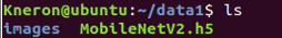
After getting the keras model, copy the model and a folder of jpg/png images which fall into the categories of ImageNet to /data1 of vm. The recommended size of images is more than 100, which the tools will use it for quantization.
Run toolchain in vm and map ~/data1 folder of vm into /data1 of toolchain
sudo docker run -it --rm -v ~/data1:/data1 kneron/toolchain:linux_command_toolchain
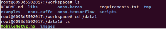
After that, we will enter toolchain docker container, and it is at workspace/. Check if the /data1 is mapped with the external folder successfully or not.
Then we can run toolchain in vm to convert the keras model into onnx model. The command is:
python /workspace/onnx-keras/generate_onnx.py -o /data1/MobileNetV2.h5.onnx /data1/keras/MobileNetV2.h5 -O --duplicate-shared-weights
Then we can see that a MobileNetV2 ONNX model is created under /data1

6.2. Model editing (remove softmax at the end)
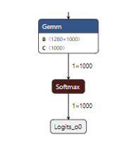
When we check the MobileNetV2 ONNX model with Netron, we can see that the network's final output layer is a softmax layer, which cannot be handled by KL520 NPU. It is very common to see the softmax layer at the end of classification network, but it is not computation extensive layer, and we can move this softmax layer into network's post process.
Toolchain provides the Python script (onnx2onnx.py) to optimize the onnx model, and the script (editor.py) to cut layers starting from a specific layer. To remove the softmax layer, we can just simply run the onnx2onnx.py as follow:
python /workspace/scripts/onnx2onnx2.py /data1/MobileNetV2.h5.onnx -o /data1/MobileNetV2_opt.h5.onnx
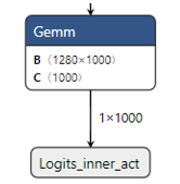
After running onnx2onnx.py script, the optimized model MobileNetV2_opt.h5.onnx is saved in /data1. The final layer of the optimized onnx model is Gemm layer now.

6.3. Model Compile Flow (compile to all_model.bin and fw_info.bin)
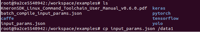
Copy the /workspace/examples/batch_compile_input_params.json into /data1 and modify it before batch-compiling MobileNetV2.
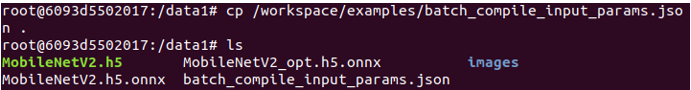
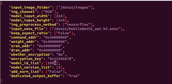
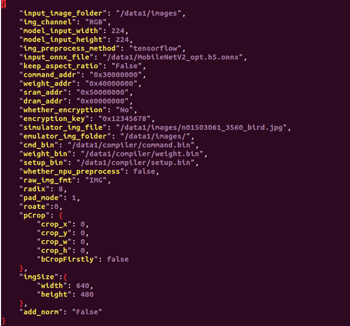
The batch_compile_input_params.json is modified as:
specify the input_image_folder to be "data1/images", this give the image folder path for the tool to do fixed point analysis.
specify the model input width and height to be "224" and "224", user needs to modify this to fit thier models input size.
tensorflow for public MobileNetV2 as img_preprocess_method. this implies using tensorflow default preprocess, which is X/127. 5 -1
specify the model "input_onnx_file" to be "/data1/MobileNetV2_opt.h5.onnx", which is the model we just edited.
Modify the model_id to be 1000 for MobileNetV2.
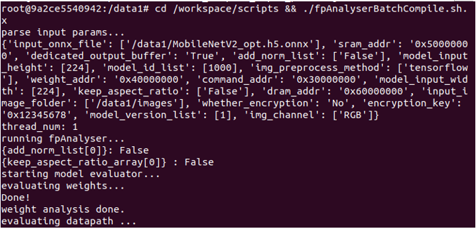
Execute the command to batch-compile MobileNetV2 model.
cd /workspace/scripts && ./fpAnalyserBatchCompiler.sh.x
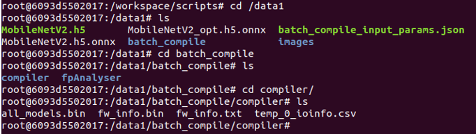
After batch-compilation, a new batch_compile folder with all_models.bin and fw_info.bin is present in /data1. These two binaries will be used for running the model in KL520 later.
6.4. Estimated NPU Run Time for Model
We can use Toolchain to get the evaluation result of NPU performance for Kneron device. The result does not include the time to do pre/post process and cpu node process. Firstly copy the input_params.json under /workspace/examples to /data1. Same as doing batch compile
Modify the input_params.json as: tensorflow for public MobileNetV2 as img_preprocess_method, False for add_norm.
Execute the command to run evaluation for MobileNetV2 model.
cd /workspace/scripts && ./fpAnalyserCompilerIpevaluator.sh.x
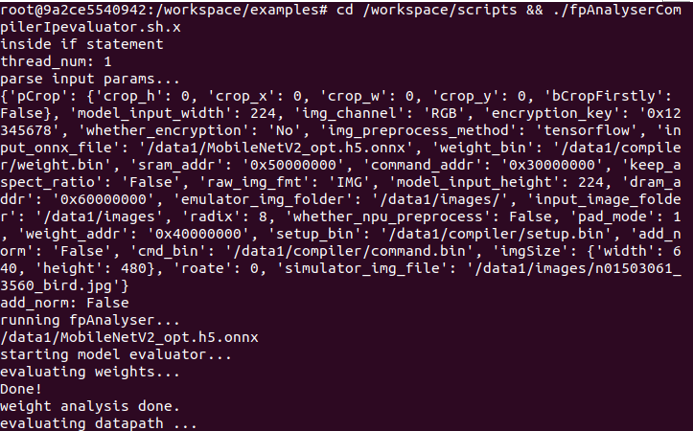
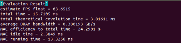
After the evaluation process is finished, we can get the evaluation_result.txt under /data1/compiler.
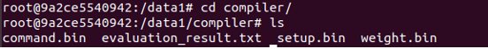
The evaluation result does not count in the time to do pre/post process and cpu node process. For this MobileNetV2 model, it will take around 15.7ms (total time)
7. Run Model Binaries in DME Mode
Please refer to the example code in example/dme_async_mobilenet_classification.cpp
7.1. DME mode Introduction
In DME mode, the test images, model binaries, and configuration are dynamically sent from host to Kneron device via USB, and the detection results are dynamically retrieved back from Kneron device to host via USB.
In host side, 5 APIs are used for DME.
| API | Description | Note |
|---|---|---|
| kdp_start_dme | Send model data of all_models.bin/fw_info.bin to Kneron device | Call once |
| kdp_dme_configure | Send DME configuration to Kneron device | Call once |
| kdp_dme_inference | Send image data to Kneron device and start inference | Call multiple times to send image for inference |
| kdp_dme_get_status | Poll the completed status from Kneron device | Call multiple times after kdp_dme_inference |
| kdp_dme_retrieve_res | Retrieve the inference result (fix-point data) back to host | Call multiple times after kdp_dme_get_status |
7.2. DME Mode Pre/Post Process
Kneron provides default pre/post process function in firmware code if it is run in DME mode.
Pre Process
The default preprocess function finish the tasks:
Reformat: Transfer original format, such as RGB565 or YUV422, to RGBA8888
Resize: Resize image size to model input size
Subtract: Subtract 128 for all data if configured
Right-shift for 1 bit if configured
Because this MobileNetV2 model needs to apply tensorflow preprocess, which is X/127.5 -1, it is similar to apply DME default pre process. In section 7.3, we will see how to config the pre process for this MobileNetV2 model.
Post Process
The default postprocess function in DME mode would send back the original output from KL520 NPU, and user needs to implement post process functions in order to get the correct result.
finish the tasks:
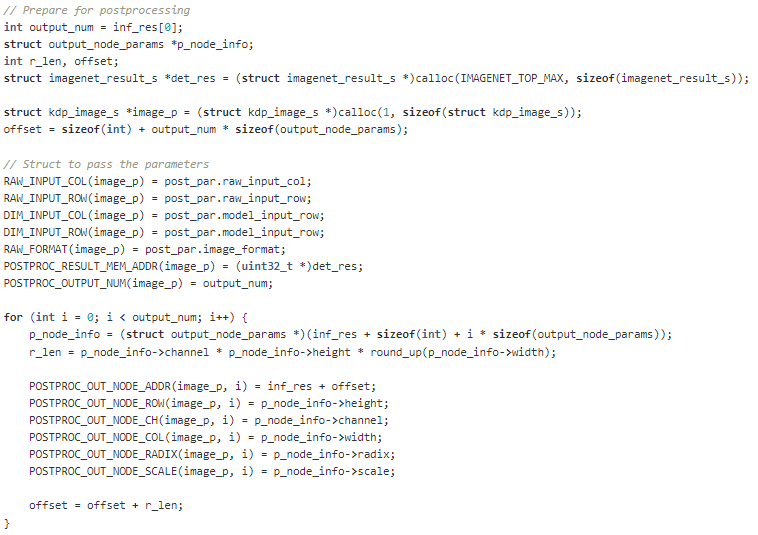
1. KL520 send the fix-point data of all output nodes to one with the sequence of total_out_number + (c/h/w/radix/scale) + (c/h/w/radix/scale) + ... + fp_data + fp_data + ...
With this data format, host needs to converts it back to a shared structure struct kdp_image_s that can easily identify each output nodes parameters, such as channel, height, width, radix, and scales.
- Host will call actual model post process function
post_imgnet_classificaiton()in example/post_processing_ex.c
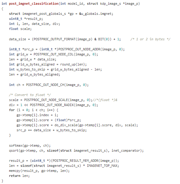
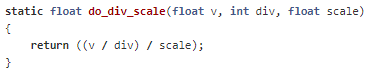
In KL520, the results are in 16-byte aligned format for each row, and these values are in fixed point. As a result, host need to convert these values back to floating by using the radix and scale value for each output node. do_div_scale() is for this purpose.
After converting all the output values back to float, host post process program need to add back the softmax layer, which was cut in model editor (onnx2onnx.py). Lastly, host use qsort to find the top N probability from the 1000 classes.

7.3. How to config DME based on the input images
After getting the parameters of input images and models, we can set DME configuration and postprocessing configuration as shown in the example code of dme_async_mobilenet_classification.cpp.
The following settings mean that the host would send 640x480 RGB565 image to KL520, and KL520 will resize it to 224x224 for model input. Then KL520 will send back raw NPU output back to Host, which suggests host side need to perform post process in order to get the results. Please note that when we compile the model in section 6, we assign model id 1000 to this MobileNetV2 model, and we need to pass this model id in the dme config as well.
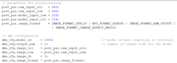
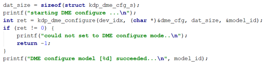
Then we can call API kdp_dme_configure() to config DME.
7.4. Run DME App
After building the example code using make -j, we can run the MobileNetV2 example in command line.

The top 5 results for each image is printed out. After finishing the inference for 100 images, the average time of each frame and the fps is calculated and printed out.
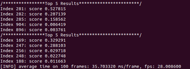
We can compare the classification index results with the index list on here: Imagenet Class Index
8. Create New SDK Application
8.1. KL520 Firmware Architecture
KL520 firmware is consisted of two bootloaders, IPL and SPL, and two RTOS (Real Time Operating System) images running on system cpu (SCPU) and NPU-assisting cpu (NCPU).
When IPL (Initial Program Loader) in ROM starts to run on SCPU after power-on or reset, it loads SPL (Secondary Program Loader) from flash (automatically or type 1 in UART menu), then SPL loads SCPU firmware image from flash, and finally SCPU firmware loads NCPU firmware image which runs on NCPU.
Both SCPU and NCPU firmware run RTOS with SCPU handling application, media input/output and peripheral drivers and NCPU handling CNN model pre/post processing. Two CPUs use interrupts and shared memory to achieve IPC (Inter Processor Communication).
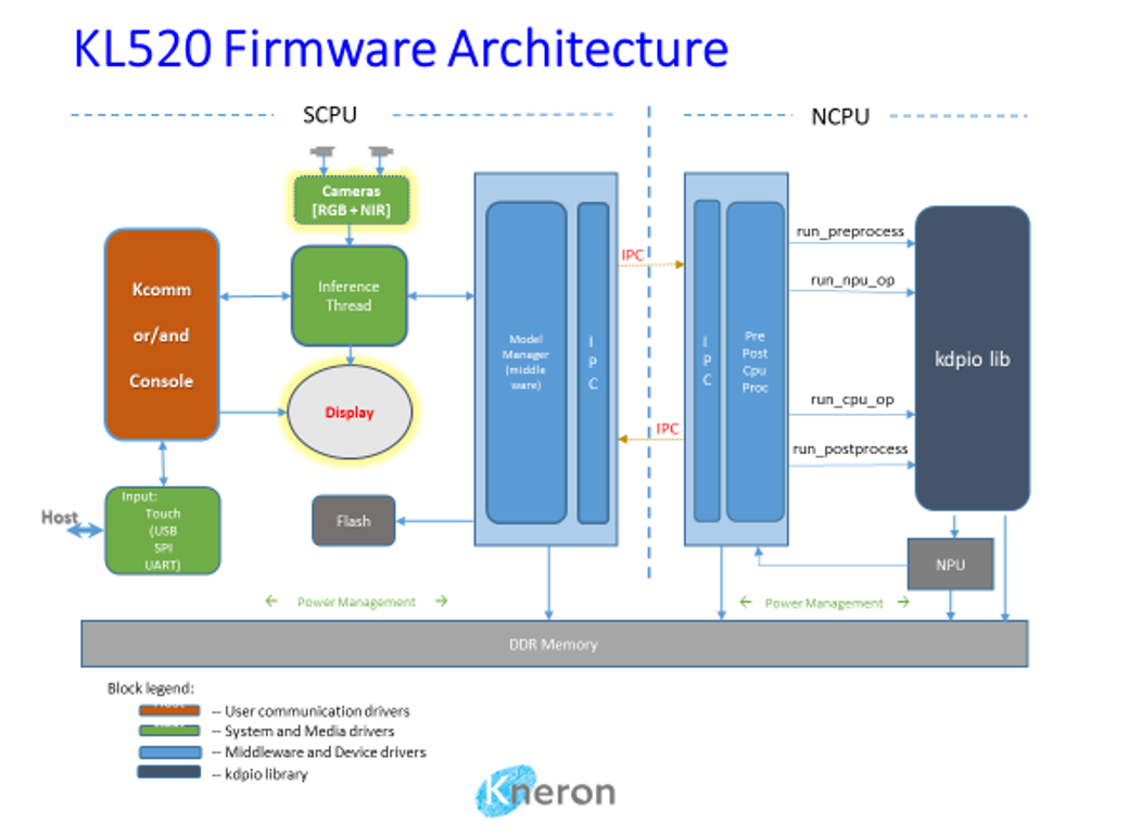
The examples of SDK here are for SCPU RTOS firmware and NCPU RTOS firmware. Both uses ARM Keil RTX.
8.2. Firmware components
- SCPU firmware:
- Project: companion or host
- a. Output: fw_scpu.bin
- Libs:
- a. sdk.lib -- system/middle/peripheral drivers
- b. kapp.lib -- FDR application lib [lib only]
- c. kdp-system.lib -- System lib [lib only]
- d. kcomm.lib -- Communication handler driver
- Project: companion or host
- NCPU firmware:
- Project: ncpu
- a. Output: fw_ncpu.bin
- Libs:
- a. kdpio-lib.lib -- NPU i/o lib [lib only]
- b. sdk-ncpu.lib -- NCPU supporting drivers
- Project: ncpu
- Workspace
- Multiple projects can be organized together
- a. example_projects/*
- A workspace includes projects from
- a. scpu/project/[APP]/[host, companion]/
- b. scpu/lib/[LIB]
- c. ncpu/project/[APP]/
- d. ncpu/lib/[kdpio, sdk-ncpu]
- Multiple projects can be organized together
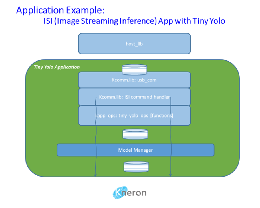
8.3. Application Architecture
An application is consisted of one or multiple CNN models for specific purposes, and corresponding preprocessing and postprocessing. There are many kinds of applications depending on specific use cases. Some application could have their image processing streamlined for best performance and some may not. Some applications could have multiple models, and some may have single model.
A host mode application means that camera(s) and maybe display are located on the same board with KL520, and a companion mode application assumes camera image comes from outside like a different chip or PC.
Tiny Yolo is a single model application with streamlined processing. Both companion mode and host mode are supported. Figure below is a companion mode example.
8.4. Create New Application Project
- Use existing application project as template
Example: ./scpu/project/tiny_yolo_v3/companion/ Copy whole directory to a new one with files like this:
scpu/project/tiny_yolo_v3/companion/RTE/CMSIS/RTX_Config.c
scpu/project/tiny_yolo_v3/companion/RTE/CMSIS/RTX_Config.h
scpu/project/tiny_yolo_v3/companion/RTE/Device/ARMCM4_FP/startup_ARMCM4.s
scpu/project/tiny_yolo_v3/companion/RTE/Device/ARMCM4_FP/system_ARMCM4.c
scpu/project/tiny_yolo_v3/companion/companion.uvoptx
scpu/project/tiny_yolo_v3/companion/companion.uvprojx
scpu/project/tiny_yolo_v3/companion/main/main.c
scpu/project/tiny_yolo_v3/companion/mozart_96.sct
scpu/project/tiny_yolo_v3/companion/post_build.bat
scpu/project/tiny_yolo_v3/companion/vtor.ini
Host mode may include more files to support UART console, camera image inference:
scpu/project/tiny_yolo_v3/host/main/main.c
scpu/project/tiny_yolo_v3/host/main/kapp_tiny_yolo_console.c
scpu/project/tiny_yolo_v3/host/main/kapp_tiny_yolo_inf.c
scpu/project/tiny_yolo_v3/host/main/kapp_tiny_yolo_inf.h
Furthermore, make sure libraries are included such as these for companion application:
kapp.lib
kdp-system.lib
kcomm.lib
sdk.lib
Host mode application may include less libraries if no communication (kapp.lib or kcomm.lib) with another chip or PC is needed:
kdp-system.lib
sdk.lib
8.5. Create New NCPU Project
- Use existing application’s Project:ncpu as template
Example: ./ncpu/project/tiny_yolo_v3/ Copy whole directory toa new one with files like this:
ncpu/project/tiny_yolo_v3/RTE/CMSIS/RTX_Config.c
ncpu/project/tiny_yolo_v3/RTE/CMSIS/RTX_Config.h
ncpu/project/tiny_yolo_v3/RTE/Device/ARMCM4_FP/startup_ARMCM4.s
ncpu/project/tiny_yolo_v3/RTE/Device/ARMCM4_FP/system_ARMCM4.c
ncpu/project/tiny_yolo_v3/main/main.c
ncpu/project/tiny_yolo_v3/ncpu.uvoptx
ncpu/project/tiny_yolo_v3/ncpu.uvprojx
ncpu/project/tiny_yolo_v3/post_build.bat
Also, must include libraries:
kdpio-lib.lib
sdk-ncpu.lib
8.6. Create New Workspace to Include All Projects
- Use existing application’s workspace as template
Copy the workspace.uvmpw file to your directory, add/remove projects as needed.
example_projects/tiny_yolo_v3_companion/workspace.uvmpw
A companion application workspace usually contains these projects:
Project:sdk
Project:kcomm-lib
Project:companion
Project:sdk-ncpu
Project:ncpu
A host application workspace usually contains these projects:
Project:sdk
Project:companion
Project:sdk-ncpu
Project:ncpu
8.7. Create ISI Companion Application
Main tasks in main.c
- Initialize OS
- Initialize SDK with companion mode
main_init(0) - Load ncpu firmware
main_load_ncpu(0) - Initialize communication module
kcomm_start()
Add operations for ISI command handler, e.g. in a shared directory/file (app/tiny_yolo_ops.c):
static struct kapp_ops kapp_tiny_yolo_ops = {
    .start          = tiny_yolo_start,
    .run_image      = tiny_yolo_run_image,
    .get_result_len = tiny_yolo_get_result_len,
};

/**
  .start: check application id at init time
  .run_image: pass image and parameters to middleware driver to
              run with the model(s) (model id TINY_YOLO_V3 here)
              of the application
  .get_result_len: tell the length in bytes of a result buffer
**/

struct kapp_ops *tiny_yolo_get_ops(void)
{
    return &kapp_tiny_yolo_ops;
}
Register new ops with ISI command handler:
struct kapp_ops *ops;

ops = tiny_yolo_get_ops();
kcomm_enable_isi_cmds(ops);
Support multiple models:
When an application includes multiple models, each model needs a separate result memory, and all result memory buffers must be allocated in DDR using kmdw_ddr_reserve() because they are filled up by NCPU.
For companion mode this can be all done in .run_image callback function like age_gender ISI example where two models (KNERON_FDSSD and KNERON_AGE_GENDER) are run one after another.
scpu/project/age_gender/app/age_gender_ops.c
Parallel image processing for NPU and NCPU:
When incoming images could be fed to NPU running model while previous image’s postposing to run on NCPU in parallel, a parallel bit can be set in image format to enable this feature.
define IMAGE_FORMAT_PARALLEL_PROC BIT27
8.8. Create Host Mode Application with MIPI Camera
Main tasks in main.c
- Initialize OS
- Initialize SDK with host mode (camera/display is initialized, ncpu firmware is loaded )
main_init(1) - Initialize application console
console_entry()
Add your application needed console/camera/display and inference controls, such as those in:
scpu/project/tiny_yolo_v3/host/main/kapp_tiny_yolo_console.c
scpu/project/tiny_yolo_v3/host/main/kapp_tiny_yolo_inf.c
scpu/project/tiny_yolo_v3/host/main/kapp_tiny_yolo_inf.hstruct kapp_ops *ops;
ops = tiny_yolo_get_ops();
kcomm_enable_isi_cmds(ops);8.9. Register New Pre/Post Processing and CPU functions
For application that using new model, users need to register the corresponding pre and post process functions. User can refer to tiny_yolo_v3_companion project's main function in ncpu.
First, user need to define an new model ID for the model. For example, TINY_YOLO_V3 is defined model ID for tiny yolo v3 model.
There is a default pre-processing function to handle scaling, cropping, rotation, 0-normalization with hardware acceleration.
If a special processing is needed for incoming raw image, this API can be called to register in void pre_processing_add(void) function.
kdpio_pre_processing_register(TINY_YOLO_V3, new_pre_yolo_v3);
Same procedure can be applied to post process as well. We need to add the following into the void post_processing_add(void) function.
kdpio_post_processing_register(TINY_YOLO_V3, new_post_yolo_v3);
Sometime, KL520 NPU cannot handle some layers in the model, and user need to implement a CPU function to complete the model. The user will require to register the cpu function so that the runtime library knows what to do during the cpu node. Users can do it in void cpu_processing_add(void) function, add the cpu funcitons:
kdpio_cpu_op_register(ZERO_UPSAMPLE, new_zero_upsample_op);
Please note that user needs to define an new cpu function ID for this cpu function.
9. More SDK example code for SOC peripheral drivers
KL520 also provides some simple examples to show how to use basic peripherals such as, I2C, PWM, DMA, GPIO... User can find them from sdkexamples folder.
There is also a PDF file to briefly describe the peripheral APIs. Please download it from the following link:
10. Flash programming
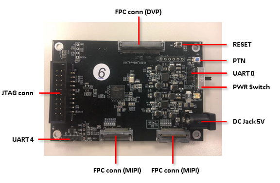
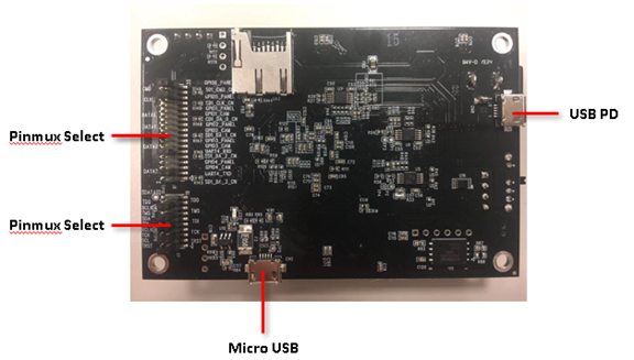
10.1. Board Overview
10.2. Hardware Setting
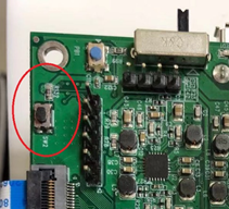
10.2.1. Connecting UART0 (Program Flash via UART0 Interface)
UART0: Command Port
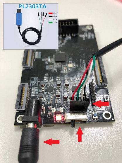
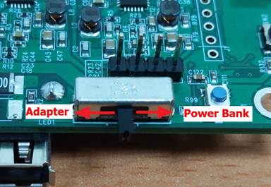
10.2.2. Connecting 5V power and trun on power switch
Power from Adapter or from Power Bank (USB PD)
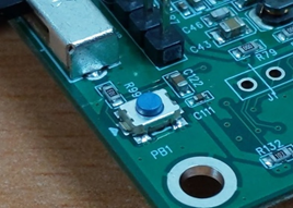
10.2.3. Wake up chip from RTC power domain by pressing PTN button
Please do it every time after plugging in the power
10.3. Program Flash via UART0 Interface
10.3.1. Flash programmer necessaries
- Open command terminal for flash programmer execution
Tool path: kl520_sdk\utils\flash_programmer\flash_programmer.py
-
Install Necessary python modules: kl520_sdk\utils\requirements.txt
-
Limitations: Only the listed argument combinations below are allowed.
10.3.2. Edit python verification setting
-
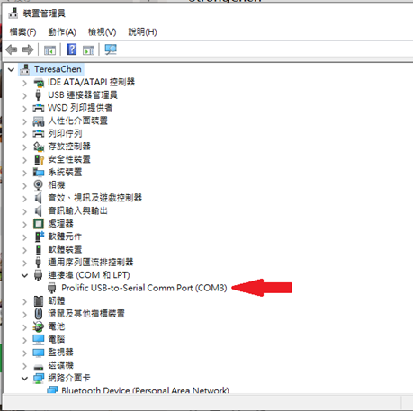
Check UART port number from device manager
-
Edit setup.py, search “COM_ID” and modify the ID to match your UART port number
EX: COM_ID = 3 # COM3
10.3.3 Flash Chip Programming (FW + DATA)
>> python flash_programmer.py -a flash_fdfr_image.bin
Please press RESET BTN while you are seeing “Please press reset button!!”
Afterwards, just wait until all progresses are finished (erase, program, verify)
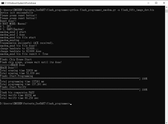
Note: "flash_programmer.py -a" means to do flash chip erase + programming + verification
10.3.4 Flash Verification (optional)
>> python flash_programmer.py -v flash_fdfr_image.bin
10.3.5 Flash Erase (optional)
>> python flash_programmer.py -e
10.3.6 Flash Partial Programming (optional)
>> python flash_programmer.py -i 0x00002000 -p fw_scpu.bin
Note: To program specific bin file to specific flash address "-i" means the flash index/address you would like to program "-p" means the FW code you would like to program
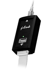
10.4. Program Flash via JTAG/SWD Interface
10.4.1. Jlink programmer necessaries
Connect JTAG/SWD.
10.4.2. Edit flash_prog.jlink device setting
-
Check your flash manufacturer: Winbond or Mxic or GigaDevice
-
Select a specific device based on flash manufacturer
EX:
device KL520-WB //Winbond
device KL520-MX //Mxic
device KL520-GD //GigaDevice
-
Copy the bin file to kl520_sdk\utils\JLink_programmer\bin folder
EX: flash_fdfr_image.bin, boot_spl.bin, fw_scpu.bin, fw_ncpu.bin, etc.
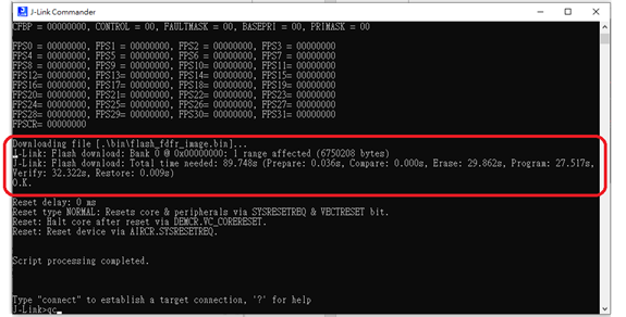
10.4.3. Double click "flash_prog.bat"
Afterwards, just wait until all progresses are finished (chip erase, program, verify)
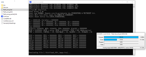
10.4.4. Check programming result
Please ensure all the results are "O.K.", and enter "qc" to quit and close J-Link commander
10.4.5. Edit flash_prog_partial.jlink device setting(optional)
To program specific bin file to specific flash address
-
Copy the bin file to kl520_sdk\utils\JLink_programmer\bin\
-
Select a specific device+’-P’ based on flash manufacturer
EX:
device KL520-WB-P //Winbond
device KL520-MX-P //Mxic
device KL520-GD-P //GigaDevice
-
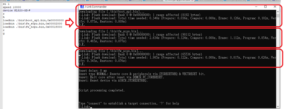
Edit loadbin command: Load *.bin file into target memory
Syntax:
loadbin <filename>, <addr>loadbin .\bin\boot_spl.bin,0x00000000loadbin .\bin\fw_scpu.bin,0x00002000loadbin .\bin\fw_ncpu.bin,0x00018000 -
Double click “flash_prog_partial.bat” and wait until all progresses are finished
-
Check programming result
Please ensure the results is “O.K.”, and enter “qc” to quit and close J-Link commander
EX: