Flash Management
1. Board Overview
-
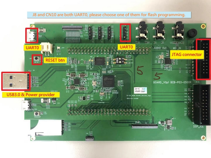
Board 96-A
-
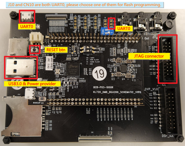
Board 96-B
2. Hardware Setting
2.1. Connecting UART0 (Program Flash via UART0 Interface)
UART0: Command Port (either CN10 or J8)
-
Board 96-A
-
Board 96-B
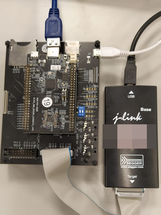
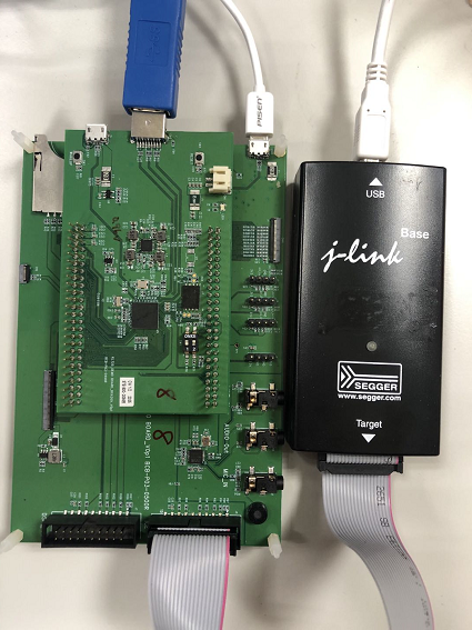
2.2. Connecting JTAG (Program Flash via JTAG/SWD Interface)
2.3. Connecting USB3.0 for 5V power supply
3. Program Flash via UART0 Interface
3.1. Flash programmer necessaries
-
Open command terminal for flash programmer execution
Tool path: kl720_sdk\firmware\utils\flash_programmer\nand\flash_programmer.py
-
install Necessary python modules: kl720_sdk\firmware\utils\requirements.txt
3.2. Edit python verification setting
-
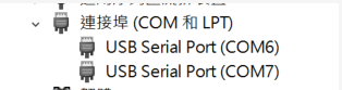
Check UART port number from device manager
-
Edit setup.py, search “COM_ID” and modify the ID to match your UART port number
ex: COM_ID = 6 # COM6
3.3 Firmware Binary Generation (FW + MODELS)
Generate flash final bin file from other seperate bin files.
The script combines .bin files in "flash_bin" in predefined order.
Morever, the addressing is in 4KB alignment.
Command:
>> python3 bin_gen.py <options>

options argument:

-h, --help      Show this help message and exit

-p, --CPU_ONLY  SPL/SCPU/NCPU only
Output:
flash_image.bin
** The following bin files are must **
flash_bin
├── boot_spl.bin // bool spl bin file
├── fw_ncpu.bin // SCPU FW bin file (generated by Keil)
├── fw_scpu.bin // NCPU FW bin file (generated by Keil)
├── models_720.nef // model information(copied from kenron_plus/res/models/KL720)
3.4 Flash Chip Programming (FW + DATA)
>> python flash_programmer.py -a flash_image.bin
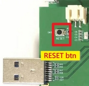
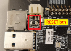
Please press RESET BTN while you are seeing “Please press reset button!!”
-
Board 96-A
-
Board 96-B
Afterwards, just wait until all progresses are finished (erase, program, verify)
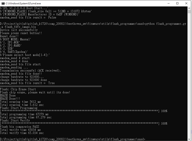
Note: "flash_programmer.py -a" means to do flash chip erase + programming + verification
3.5 Flash Verification (optional)
>> python flash_programmer.py -v flash_image.bin
3.6 Flash Erase (optional)
>> python flash_programmer.py -e
3.7 Flash Partial Programming (optional)
>> python flash_programmer.py -i 0x00040000 -p fw_scpu.bin
Note: To program specific bin file to specific flash address "-i" means the flash index/address you would like to program "-p" means the FW code you would like to program
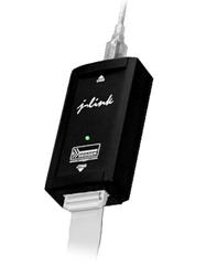
4. Program Flash via JTAG/SWD Interface
4.1. Jlink programmer necessaries
Connect JTAG/SWD and USB3.0 for 5V power.
4.2. Edit flash_prog.jlink device setting
-
Check your flash type: Winbond SPI Nand flash
-
Select a specific device based on flash manufacturer EX: device KL720-WB-NAND //Winbond Nand flash
-
Copy the bin file to kl720_sdk\firmware\utils\JLink_programmer\bin folder EX: flash_image.bin, boot_spl.bin, fw_scpu.bin, fw_ncpu.bin, fw_ncpu_dram.bin etc.
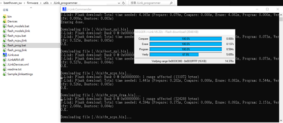
4.3. Double click "flash_prog.bat"
Afterwards, just wait until all progresses are finished (chip erase, program, verify)
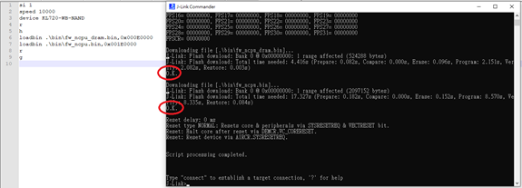
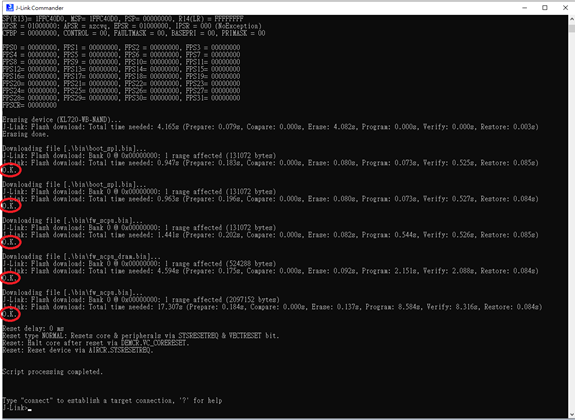
4.4. Check programming result
Please ensure all the results are "O.K.", and enter "qc" to quit and close J-Link commander
4.5. Edit flash_prog_partial.jlink device setting(optional)
To program ncpu fw partially to specific flash address(sector erase, program, verify)
-
"flash_ncpu.jlink" loadbin command: Load *.bin file into target memory
Syntax:
loadbin <filename>, <addr>loadbin .\bin\fw_ncpu_dram.bin,0x000E0000loadbin .\bin\fw_ncpu.bin,0x001E0000 -
Double click “flash_ncpu.bat” and wait until all progresses are finished
-
Check programming result Please ensure the results is “O.K.”, and enter “qc” to quit and close J-Link commander EX: