Flash Management
1. Board Overview
-
Board 96-A
-
Board 96-B
2. Hardware Setting
2.1. Connecting UART0 (Program Flash via UART0 Interface)
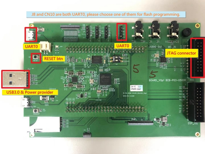
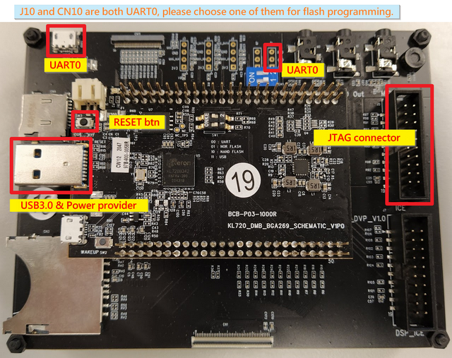
UART0: Command Port (either CN10 or J8)
-
Board 96-A
-
Board 96-B-9x9 / 96-B-11x11
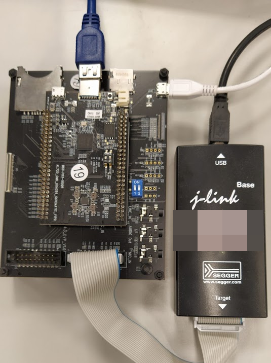
2.2. Connecting JTAG (Program Flash via JTAG/SWD Interface)
2.3. Connecting USB3.0 for 5V power supply
2.4. Bootstrap Settings
Board 96-A
| bootstrap | graphical |
|---|---|
| 00: UART | 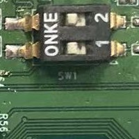 |
| 01: NOR FLASH | 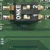 |
| 10: NAND FLASH | 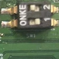 |
| 11: USB | 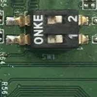 |
Board 96-B-9x9
| bootstrap | graphical |
|---|---|
| 00: UART | 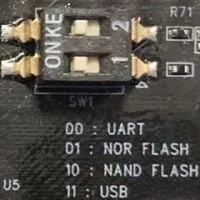 |
| 01: NOR FLASH | 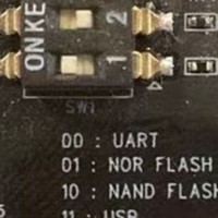 |
| 10: NAND FLASH | 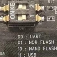 |
| 11: USB | 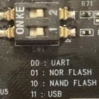 |
Board 96-B-11x11
| bootstrap | graphical |
|---|---|
| 00: UART | 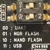 |
| 01: NOR FLASH | 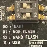 |
| 10: NAND FLASH |  |
| 11: USB | 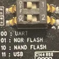 |
3. Program Flash via UART0 Interface
3.1. Flash programmer necessaries
- set bootstrap as "UART"
- Open command terminal for flash programmer execution
Tool path:
kl720_sdk\firmware\utils\flash_programmer\nand\flash_programmer.py - install Necessary python modules: kl720_sdk\firmware\utils\requirements.txt
- Limitations: Only the listed argument combinations below are allowed.
3.2. Edit python verification setting
-
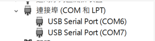
Check UART port number from device manager
-
Edit setup.py, search “COM_ID” and modify the ID to match your UART port number
EX: COM_ID = 6 # COM6
3.3 Firmware Binary Generation (FW + MODELS)
Generate flash final bin file from other separate bin files. The script combines .bin files in "flash_bin" in predefined order. Binary placing offset for KL720 flash should align with 128KB (NAND) / 4KB (NOR)
Command
$ python3 bin_gen.py <options>

    options argument:

    -h, --help      Show this help message and exit
    -p, --CPU_ONLY  FW only without model
    -f FLASH_SIZE, --flash_size FLASH_SIZE
                        target board flash size in MB
    -r, --nor       nor type flash
Output
flash_image.bin
Note
-
Component, nef_utility, is used by bin_gen. If in Linux, must
chmod +x ../nef_utility/nef_utility_linuxfirst -
The following bin files are must
flash_bin
├── boot_spl.bin      // bool spl bin file (for NAND flash)
├── boot_sp_nor.bin   // bool spl bin file (for NOR flash)
├── fw_ncpu.bin       // SCPU FW bin file (generated by Keil)
├── fw_scpu.bin       // NCPU FW bin file (generated by Keil)
├── models_720.nef    // model information(or copied from kenron_plus/res/models/KL720)
3.4 Flash Chip Programming (FW + DATA)
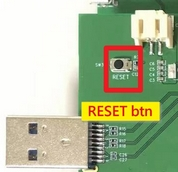
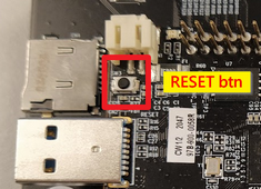
$ python flash_programmer.py -a flash_image.binPlease press RESET BTN while you are seeing “Please press reset button!!”
-
Board 96-A
-
Board 96-B
Afterwards, just wait until all progresses are finished (erase, program, verify)
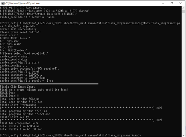
Note
flash_programmer.py -ameans to do flash chip erase + programming + verification
3.5 Flash Verification (optional)
$ python flash_programmer.py -v flash_image.bin3.6 Flash Erase (optional)
$ python flash_programmer.py -e3.7 Flash Partial Programming example (optional)
$ python flash_programmer.py -i 0x00040000 -p fw_scpu.bin

# "**-i**" means the flash index/address to program
# "**-p**" means the FW binary to program
3.8 Program to Nor flash
The above 3.4 ~ 3.7 are used for nand flash by default. If the project design uses nor flash, please add the '-r' parameter.
$ python flash_programmer.py -r -a flash_image.bin
$ python flash_programmer.py -r -v flash_image.bin
$ python flash_programmer.py -r -e
$ python flash_programmer.py -r -i 0x00040000 -p fw_scpu.bin
4. Program Flash via JTAG/SWD Interface
4.1. Jlink programmer necessaries
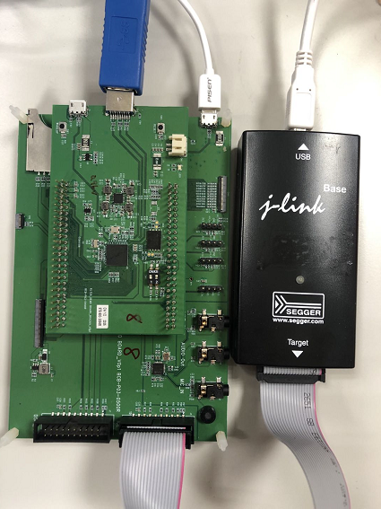
Connect JTAG/SWD and USB3.0 for 5V power.
4.2. Edit flash_prog.jlink device setting
-
Check your flash type: Winbond SPI Nand flash
-
Select a specific device based on flash manufacturer EX: device KL720-WB-NAND //Winbond Nand flash
-
Copy the bin file to
kl720_sdk\firmware\utils\JLink_programmer\binfolder EX: flash_image.bin, boot_spl.bin, fw_scpu.bin, fw_ncpu.bin, etc.
4.3. To Program composed flash_image.bin
Check existence of bin/flash_image.bin composed by utils/bin_gen in previous steps
Afterwards, just wait until all progresses are finished (chip erase, program, verify)
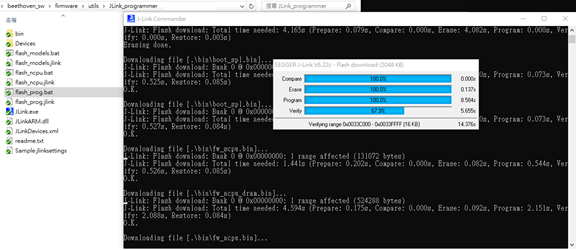
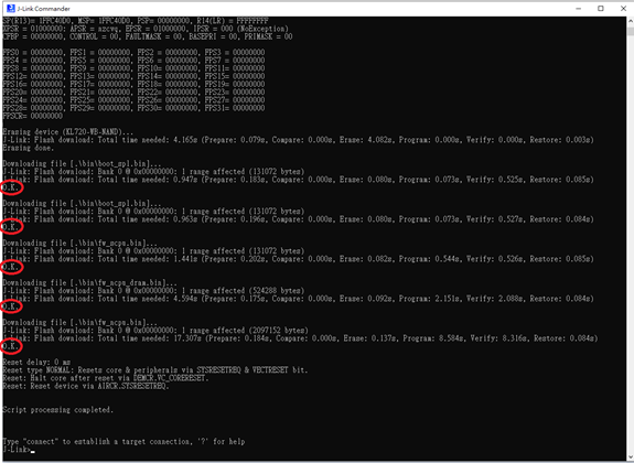
4.4. Check programming result
Please ensure all the results are "O.K.", and enter "qc" to quit and close J-Link commander