How to Interpret Fixed-Point Report
After running the fixed-point analysis step described in the toolchain manual, you would find model_fx_report.html.
This document describes how to interpret the report. The report is divided into two sections: summary and node
information table.
Summary
The summary will show the IP evaluator information. Below are some examples of report:
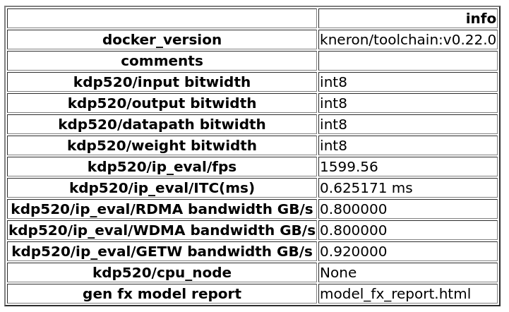
Figure 1. Summary for platform 520, mode 0 (IP evaluator only)
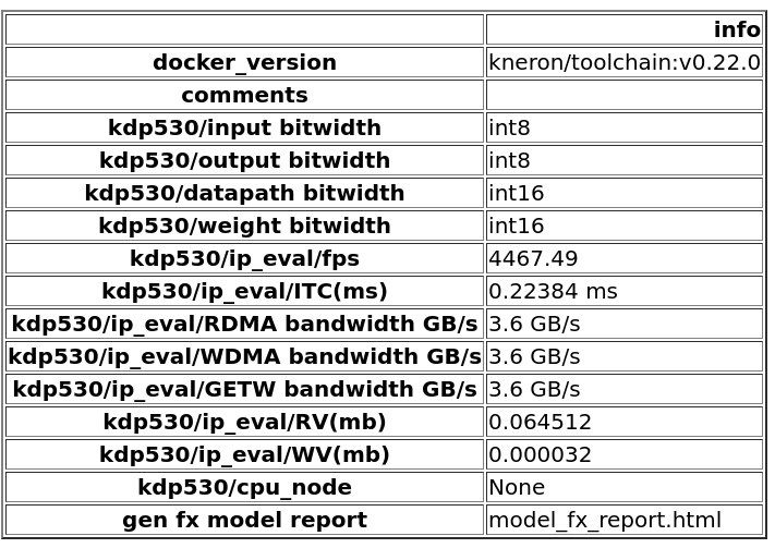
Figure 2. Summary for platform 530, mode 0 (IP evaluator only)
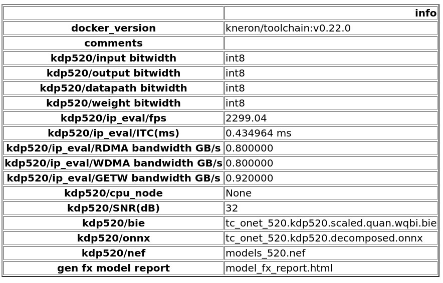
Figure 3. Summary for platform 520, mode 1 (with fixed-point model generated)
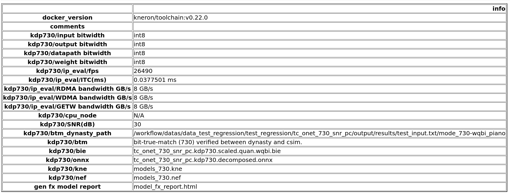
Figure 4. Summary for platform 730, mode 2 (with fixed-point model generated and snr check.)
| name | explanation | availability |
|---|---|---|
| docker_version | the version of the toolchain docker for this report | |
| comments | extra information | |
| input bitwidth | customer set input bitwidth: int8 or int16 | |
| output bitwidth | customer set output bitwidth: int8 or int16 | |
| datapath bitwidth | customer set data bitwidth (or activation bitwidth): int8 or int16 | |
| weight bitwidth | customer set weight bitwidth: int8 or int16 or int4. int4 only for certain HW. | |
| fps | estimated frame per second. | |
| ITC | estimated inference time. | |
| RDMA bandwidth | set effective peak RDMA bandwidth based on HW | |
| WDMA bandwidth | set effective peak WDMA bandwidth based on HW | |
| GETW bandwidth | set effective peak weight loading bandwidth based on HW | |
| RV | Total data load (except weight load) from DDR in one inference | |
| WV | Total data write to DDR in one inference | |
| cpu node | CPU node in model will be listed here | if any cpu node exists |
| SNR(dB) | The snr of fix point model inferenced results. | mode 2 and 3 |
| btm_dynasty_path | path to inferenced results | mode 2 and 3 |
| btm | check the bit-true-match between dynasty and csim inference | mode 2 and 3 |
| bie | generated bie file (fix point model) for dynasty inference | mode 1/2/3 |
| nef | generated nef file (fix point model) for csim / dongle inference | mode 1/2/3 |
| backend node graph | the graph after node fusion and decomposition, with backend node information. | |
| gen fx model report | file name of this report |
Node information table
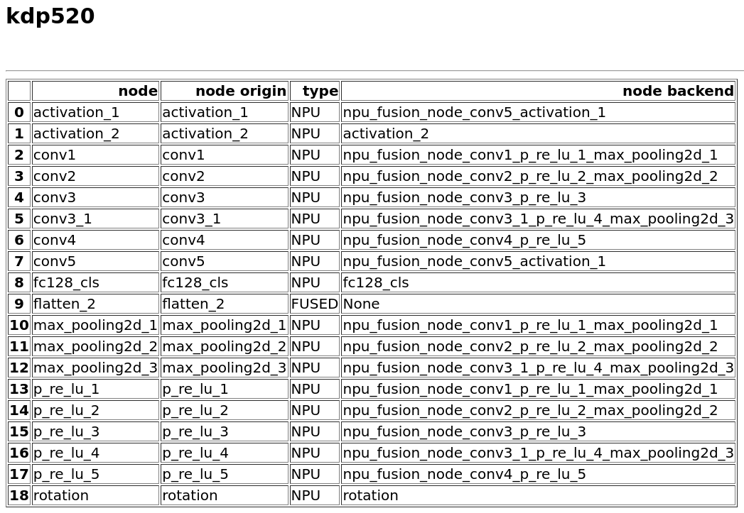
Figure 5. Node details for platform 520, mode 0 (IP evaluator only).
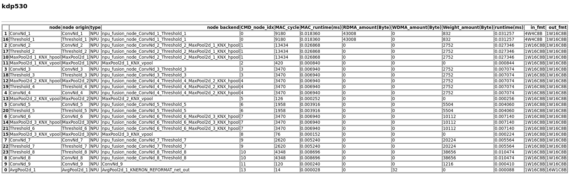
Figure 6. Node details for platform 530, mode 0 (IP evaluator only).
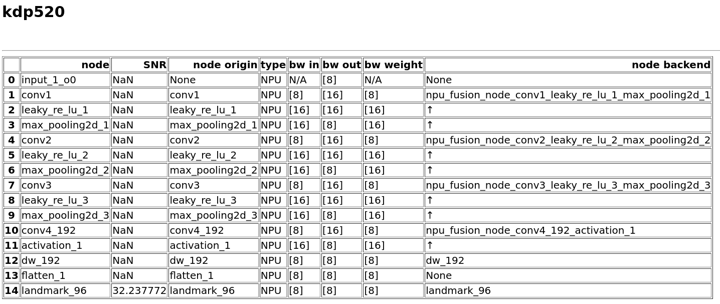
Figure 7. Node details for platform 520, mode 1 (with fixed-point model generated).
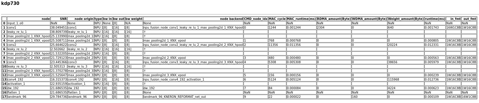
Figure 8. Node details for platform 730, mode 2 (with fixed-point model generated and SNR check).
| column | explanation | availability |
|---|---|---|
| node | model operation node name after node fusion and decomposition | |
| SNR | SNR score between fixed-point model and original model (per layer) | every layer for mode 3 and only output layer for mode 2 |
| node origin | corresponding operation node name in original onnx before node fusion and decomposition | |
| type | NPU / FUSED / CPU | |
| node backend | corresponding backend node name | |
| CMD_node_idx | index of command node | below info not available for 520 |
| bw in / bw out / bw weight | input / output / weight bitwidth for this node | mode 1 / 2 / 3 |
| MAC_cycle | MAC engine runtime cycle number for this backend node. | |
| MAC_runtime(ms) | MAC engine runtime for this backend node. | |
| RDMA_runtime(ms) | RDMA runtime for this backend node. | |
| RDMA_amount(Byte) | RDMA amount for this backend node. | |
| WDMA_runtime(ms) | WDMA runtime for this backend node. | |
| WDMA_amount(Byte) | WDMA amount for this backend node. | |
| Weight_amount(Byte) | weight amount for this backend node. | |
| CFUNC_runtime(ms) | runtime of main computing unit, including Conv and other compute operations. | |
| PFUNC_runtime(ms) | runtime of auxiliary computing unit, including pooling and data layout operations. | |
| runtime(ms) | NPU runtime of all units without sync. It's the sum of CFUNC_runtime, PFUNC_runtime, RDMA_runtime and WDMA_runtime. | |
| SYNC_runtime(ms) | NPU runtime with sync (e.g. Conv and DMA operations run at same time). This is more close to the actual runtime. | |
| in_fmt / out_fmt | input/output data formats. If only one input/output or multiple inputs/outputs with same format, the only format will be shown. If multiple formats for this node, then the details will be listed as “FORMAT1:IN1,IN2 FORMAT2:IN3”. |