Introduction
note: SDK v2.2.x is compatible with Kneron PLUS v2.2.x
note: SDK v2.x.x is NOT COMPATIBLE to v1.x.x
This document mentions the usage of prebuilt features, how to customize a model application, and peripheral features
1. Prerequisite
Hardware:
Board with KL520 chip. Ex. 520 dongle, 96board, m.2 board
(For applications with MIPI camera/Display) Kneron KL520 series AI SoC Development Kit
Software:
required OS: native Windows 10-x86_64 64-bit
licensed software: ARM Keil MDK / ARM Keil/MDK docs
2. File Structure
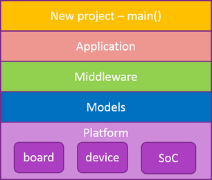
The firmware folder structure is architected with modularize and stratification for all source code. Source code belonged to the same feature is put in a dedicated folder and easy to be included or excluded. Refer to basic FW architecture shown below, the listed items will have corresponding folders.
.
└── firmware
    ├── app                                          # model flow control example
    ├── build
    │   ├── example_kdrv                             # some middleware/driver examples
    │   ├── lib/system_520/include
    │   ├── solution_XXX                             # solution examples
    ├── include                                      # high level header files
    ├── lib                                          # libraries
    │   ├── kdp2_ncpu_model_ppp.lib                  #   header file: plateform/kl520/ncpu/drv/include
    │   ├── kdp2_ncpu_sdk.lib                        #   header file: plateform/kl520/ncpu/model_ppp/include
    │   └── system_520.lib                           #   header file: build/lib/system_520/include
    ├── mdw                                          # middleware source code
    ├── platform
    │   ├── board                                    # board configuraiton header files
    │   ├── dev                                      # device drivers
    │   └── kl520                                    # chip API interface
    │       ├── common
    │       ├── ncpu
    │       │   ├── drv                              # ncpu driver API
    │       │   ├── model_ppp                        # ncpu builtin pre/post process API
    │       │   ├── rtos/rtx
    │       │   └── startup
    │       └── scpu
    │           ├── drv                              # ncpu driver API and source code
    │           ├── rtos/rtx
    │           ├── startup
    └── utils
        ├── bin_gen
        ├── dfu
        ├── minion
        ├── flash_programmer
        ├── FLM
        ├── JLink_programmer
        ├── nef_utility
        └── pinmux_config/Kneron_pinmux_config.xlsm
2.1 Folder Tree Root - 'firmware'
firmware: Contains all device FW source/lib code, utilities, build environment
└───firmware
    ├───app         # source code for application layer
    ├───build       # Build environment. Include (Keil) project files, project dependent source code.
    ├───include     # C header files for all source code
    ├───mdw         # Middleware. It's kind of "service", "manager". EX, software timer, DFU function, memory management, etc.
    ├───platform    # Platform consists of an SoC, a PCB, and some onboard devices(flash, eeprom...).
    └───utils       # some useful utilities, such as flash programming, calculate checksum...
In general, firmware source_code = app + mdw + platform(+include).
Source code is suggested to be put in these 3 folders and will not be influenced by any projects. That is, it's a source code data base. All project related code will be put under build folder.
2.2 'firmware/build'
There are some components in build folder, example projects and solution projects. As the name implies, small app demo, simple peripheral drivers demo, or any features demonstration belong to example projects. The purpose is to show how to use our SDK. Solution projects is solution examples for customer. It contains more features, or complex functions in a single project. Also, If you need to build a library and share with other projects, create lib projects in lib folder.
└────firmware/build
    ├───example_kdrv    # keil projects and example code for example projects
    ├───lib             # Keil projects and header files for prebuilt libraries
    └────solution_**    # Keil projects for example solutions
2.3 'firmware/mdw'
firmware/mdw collects independent modules to become middle ware here.
It can be generic flash driver, firmware upgrade manager, file system, etc.
└────firmware/mdw
    ├───console
    ├───dfu
    ├───flash
        ...
2.4 'firmware/platform'
firmware/platform collects board, device drivers, SoC chip drivers, OS interface, etc.
Platform = board + dev + ASIC-KL520
ASIC-KL520 is composed of 2 cores:
| Core | OS | Description |
|---|---|---|
| SCPU(ARM CM4) | Keil RTX | system flow control and handle data in/ data out via provided drivers |
| NCPU(ARM CM4) | Keil RTX | handle pre/post process and trigger NPU core to run a model |
└───firmware/platform
    ├───board              # PCB information, flash size, IO mapping, and board level configuration
    |
    ├───dev                # device drivers, such as drivers for flash, eeprom, panel, sensor, etc.
    │   ├───panel
    │   └───nand
    |       ...
    └────kl520             # KL520 SoC
        ├───common         # shared header files
        ├────scpu
        |    ├───drv       # all peripheral drivers
        |    ├───rtos      # Keil RTX operation system
        |    └───startup   # startup assembly code
        └────ncpu
             ├───drv       # prebuilt driver liberary
             ├───model_ppp # prebuilt model pre/post process functions
             ├───rtos      # Keil RTX operation system
             └───startup   # startup assembly code
2.5 'firmware/utils'
| Utility | Description | References |
|---|---|---|
| bin_gen | To generate single image from several image components | ch 3.3 in README |
| dfu | To satisfy flash address alignment. It is called by post_build.bat in each Keil project Note: Need to chmod +x gen_dfu_binary_for_linux if in linux |
See readme.txt |
| flash_programmer | Tool to program firmware/model/data via UART interface | ch 3.4 in README |
| JLink_programmer | Script to program firmware/model/data via JLink | ch 4 in README |
| nef_utility | utility for model(NEF file) Note: Need to chmod +x nef_utility_linux if in linux |
execute nef_utilty -h |
| pinmux_config | pinmux table | See kneron_pinmux_config.xlsm |
| FLM | To enable 'load' icon to program flash via JLink in Keil MDK | See README.md |
| minion | Allows device to boot from uart without external flash | See README.txt |
3. Construct a Customized AI Application
This section describes the concept of customization on input/output interface by modifying the firmware example which takes USB interface to communicate with PC via Kneron PLUS.
Below is a recommended flow of AI application construction:
- Prepare your AI model(s)
- Convert and verify model(s) via Kneron Toolchain
- With a PC, it is convenient to verify converted NEF models and easy to test variant data on target device via Kneron PLUS
note: If your application is designed as host-companion architecture with USB interface, you can stop here and go ahead with Kneron PLUS.- See Kneron PLUS - generic inference for model-only verification
- See Kneron PLUS - customized API for model and pre/post process function implementation.
- Replace implementation of data Input and result output flow according to application requirement if your application is not designed as host-companion architecture. That's to replace the related code for data-in/data-out over USB interface which is designed for Kneron PLUS control protocol library by your implementation.
For example, to consider an application which requires a connected MIPI sensor to chip as image source and output result through UART interface.
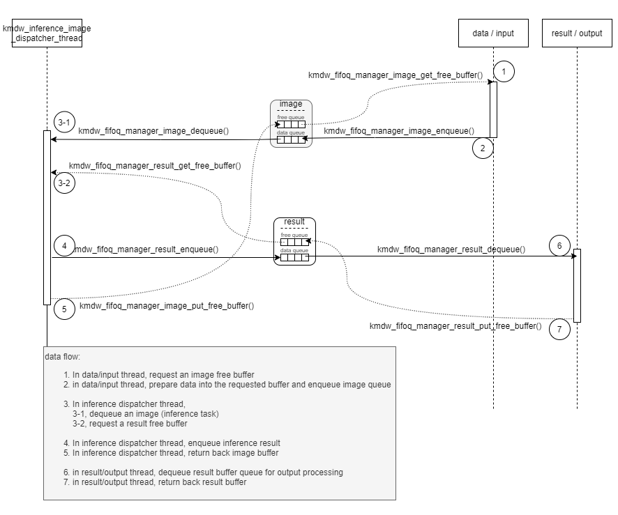
After step 1-3, implementation of model inference flow and verification is done. Refer to the diagram below. The inference flow behind kmdw_inference_image_dispatcher_thread is verified and ready. All you have to do is to modify the firmware, solution_kdp2_user_ex, which is used with Kneron PLUS for model verification by replacing the threads for data/input and result/output to become a customized firmware. The implementation is easy by calling kmdw_fifiq_manager_XXX() APIs to arrange data flow for inference tasks.
Cross reference for the modification:
| FW for Kneron PLUS (As the start FW) |
FW for MIPI in and UART out (Example of modification) |
Description/key information | |
|---|---|---|---|
| Solution | solution_kdp2_user_ex | solution_kdp2_host_in_uart_out | |
| Thread table | .../main_scpu/include/task_handler.h | <- the same | In section, "Application specific threads", Replace input/output thread settings |
| Application Entry | .../mdw/usb_companion/kdp2_usb_companion.c kdp2_usb_companion_init() |
.../main_scpu/kdp2_host_in_uart_out.c kdp2_host_in_uart_out_init() |
Config fifiq size/count kmdw_fifoq_manager_store_fifoq_config() load mode kmdw_model_load_model() |
| data/input thread | kdp2_usb_companion_image_thread() | kdp2_host_recv_uart_cmd_thread | image source handling enqueue image to image fifoq |
| result/output thread | kdp2_usb_companion_result_thread() | kdp2_host_update_result_thread() | result handling dequeue result from result fifoq |
| other thread | none | kdp2_host_recv_usb_cmd_thread() |
Note:
The KL520 firmware for Kneron PLUS is built to work with firmware loader by default. It is designed for the flexibility on dynamic firmware change.
However, for a fixed design, firmware loader feature is dummy. Please see here to know how switch to no-fw-loader flow.
4. Solution Project Examples
This SDK provides the following solution project examples.
| Solution Project | Required Chip | Peripherals | Description | Document Link |
|---|---|---|---|---|
| solution_kdp2_user_ex | kl520 | none | data input and result output via Kneron PLUS API and customized model inference flow | link |
| solution_kdp2_hico_mipi | kl520 | Kneron KL520 series AI SoC Development Kit | image from MIPI camera sensor and output to connected PC via USB | link |
| solution_kdp2_host_mipi | kl520 | Kneron KL520 series AI SoC Development Kit | image from MIPI camera sensor and output on display | link |
| solution_kdp2_host_in_uart_out | kl520 | Kneron KL520 series AI SoC Development Kit | image from MIPI camera sensor and output to connected PC via UART | link |
General common files:
- Keil project path: ./firmware/build/soluiton_XXX
- version info file: ./firmware/include/version.h
- project configuration: ./firmware/build/solution_xxx/sn520xxx/project.h
5. SoC Peripheral Drivers
The list of peripherals for the application programming reference.
Supported/Unsupported Peripheral Table
Companion means controlled by a host PC through USB by Kneron PLUS APIs
Image Input
| Peripherals | Companion | Host Mode |
|---|---|---|
| MIPI CSI RX | x | O |
| DVP | x | driver/example |
| UVC Host | x | specified cameras |
| USB(proprietary) | O | x |
| SPI Master, non-DMA | x | driver/example |
| SPI Slave, non-DMA | x | driver/example |
| SPI Master, DMA | x | x |
| SPI Slave, DMA | x | x |
| UART | x | x |
Image/Result Output
| Peripherals | Companion | Host Mode |
|---|---|---|
| MIPI DSI TX | x | x |
| MIPI CSI TX | x | x |
| DVP | x | O |
| UVC device | x | x |
| USB bulk | x | O |
| USB(proprietary) | O | x |
| SPI Master, non-DMA | x | driver/example |
| SPI Slave, non-DMA | x | driver/example |
| SPI Master, DMA | x | x |
| SPI Slave, DMA | x | x |
| UART | x | O |
| I2C | x | driver/example |
| I2S | x | x |
| INTEL 8080 | x | x |
Appendix
| Item | Description | References |
|---|---|---|
| No-FW-loader flow | How to use no-firmware-loader flow | link |
| No-Flash Design | Support uart boot and no-flash design | link |